|
|
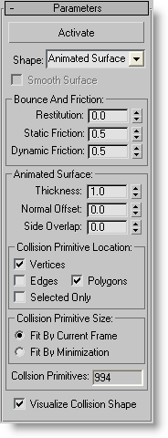
PFlow Collision Shape (WSM) ModifierPath: Select one or more objects > Modify panel > Modifier List > World-Space Modifiers section > Click PFlow Collision Shape (WSM). PFlow Collision Shape is a world-space modifier (WSM) that enables standard mesh objects to participate as particle deflectors in the PhsyX simulation. Usage is straightforward: Apply the modifier to all objects that should deflect particles, and then add the modified objects as deflectors to a PhysX Collision test. Also, you can bind particles to the deflector with PhysX Glue, but, again, the deflector must be specified as such with a PhysX Collision test in the same event as the PhysX Glue test. Note: PFlow Collision Shape works with primitive objects as well as objects in editable poly and editable mesh formats. However, it uses the editable mesh format internally, so to take full advantage of its capabilities, use it with editable mesh objects. In particular, you can use the editable mesh function to hide edges to control how the Animated Surface option creates Polygon primitives. Note: Objects with this modifier applied can interact with particles in the simulation, but not with each other. If you want disparate mesh objects to interact with each other in the simulation, set them to act as particles with the Birth Group operator. Interface Activate - Click to fix the parameters of the deflector mesh and make it available to the simulation. Activate remains on until you click it again to turn it off. Turn off to change parameters of the Collision Shape test as well as of the collision mesh object and any other modifiers applied to it. When off, the object is not available to the PhysX simulation. Note: When using the Animated Shape option (see following), Activate is available only when one or more of the three primary Collision Primitive Location options are on: Vertices, Edges, and Faces. For details, see Collision Primitive Location group, following. Shape - Choose the shape that Particle Flow uses for collision purposes. This shape is automatically applied to the object, and is visible when Visualize Collision Shape is on. The choices are: Animated Surface, Box, Capsule, Convex Hull, Geometry, Plane, and Sphere. Use the Animated Shape option for objects whose shape changes during the animation; for example, a plane animated with the Noise modifier. By default, when you choose this option, viewports and render output show only sub-objects activated for collision. For details, see Collision Primitive Location group, following. Note: The Convex Hull shape cannot contain more than 255 faces. If you attempt to use it with an object whose convex hull would contain more than 255 faces, such as the default Sphere primitive, a message appears notifying you that the software cannot create the convex mesh geometry. If this happens, either simplify the mesh shape or use a different Shape setting. Smooth Surface - Defines how the collision shape is considered for the simulation. When off, the simulation engine considers the shape to have "sharp" edges; when on, the shape is considered as an approximation of a smooth shape; thus particles that strike it can roll on its surface with sphere-like properties. Important: Smooth Surface is applicable only when a dynamic sphere rolls on a deflector composed of triangles. Thus, in general, use the Smooth Surface option only in the following situation: PhysX Shape > Collide As is set to Sphere, and PFlow Collision Shape > Shape is set to Convex Hull or Geometry. Given these conditions, using Smooth Surface can result in more-stable simulations. Otherwise, leave it off. Bounce and Friction groupNote: These settings determine how the deflector interacts with particles in the simulation, so are meaningless in isolation. To determine the actual value for an interaction, the software takes the average of the properties of the interacting elements. Restitution - The amount of energy each particle retains after a collision. Typically this produces a bouncing effect. Setting this to 1.0, the maximum value, potentially results in a condition that satisfies Newton's third law: To every action there is an equal and opposite reaction. When Restitution is close to 1.0, the bounce effect is pronounced, but as a result, not much energy is dissipated during a collision, and the dynamics solution might lack stability. Use values close to 1.0 at your own risk: when you have a small number of colliding objects, and they don't bundle together. Static Friction - The force that resists motion between two non-moving surfaces (particles and the collision shape). Dynamic Friction - The force that resists motion between two moving surfaces (particles and the collision shape). Animated Surface groupThese settings are available only when Shape is set to Animated Surface. Thickness - The extent of collision primitives (sub-objects, set in the Collision Primitive Location; see following) in the direction perpendicular to the geometry surface. For sphere collision primitives it's their diameter; for capsules it's also their diameter; for boxes/convex hull plates it's their thickness. Normal Offset - Moves collision primitives in the direction perpendicular to the geometry surface. The collision primitives should have some thickness in order to work properly as collision shapes. Because the thickness of the collision primitives can offset the visual collision surface, you can counter that by moving primitives inwards, using negative offset values. Side Overlap - Available only when Collision Primitive Location > Faces is on. This parameter defines the distance to extend the "armor plates" primitives sideways. It allows you to create overlap between the "armor plates," thus avoiding the possibility of particles passing through the animated collision surfaces. Note: due to the way the PhysX collision primitives are created out of the surface polygons, there is a limitation/correlation between the Side Overlap and Thickness parameters: the Thickness value should be at least twice that of Side Overlap value. The software takes care of this automatically: If you increase the Side Overlap value, it checks whether the Thickness value is high enough, and if not, it is increased. Collision Primitive Location groupBecause the software cannot use an arbitrary animated surface (such as a subdivided box animated with the Bend modifier) as a deflector in a simulation, setting Shape to Animated Surface enables the approximation of an animated surface by animating a set of elementary collision shapes: spheres, capsules, and convex hulls. The modifier places these shapes at appropriate positions automatically, based on sub-object locations in the animated object. Tip: Using the collision primitives alters the appearance of the animated surface, but you can make them invisible (typically for rendering purposes) by turning off Visualize Collision Shape at the bottom of the rollout. Use these toggles to specify which of these elementary collision shapes the software should use as a basis for the animated collision surface. To adjust their sizes and relative positions, use the Thickness, Normal Offset, and Side Overlap settings (see preceding). You can use any combination of the following: Vertices - Places a sphere primitive at each vertex location in the animated object. When a particle strikes any of these spheres, a collision is detected. Edges - Places a capsule primitive at each edge location in the animated object. When a particle strikes any of these capsules, a collision is detected. Polygons - Places a convex hull primitive at each polygon location in the animated object. When a particle strikes any of these hulls, a collision is detected. You can adjust the polygon configuration by hiding and unhiding surface edges. Consider the example in the included file PFlowCollisionShapeMod02.zip. The geometry for collision is a cylinder that bends sideways. If you turn off the PFlow Collision Shape and Bend modifiers in the stack, you can examine the visuals of the cylinder geometry: A number of the side edges were made invisible (Note: This is possible only with editable mesh objects, not editable poly). As a result, applying the PFlow Collision Shape modifier creates only 18 collision primitives: one for each polygon of the geometry, even if the polygon is curved. Thus, adjusting visible edges on the geometry surface becomes a way to control the shapes and number of collision primitives created for the Animated Surface type. Selected Only - When on, places the collision primitives only at the locations of selected sub-objects. For example, to have collision polygons on only one side of an object, convert the base object to an editable mesh or editable poly (or apply the corresponding modifier), go to the Polygon sub-object level, and select the faces with which particles should collide. Then, at the level of the PFlow Collision Shape modifier, set Shape to Animated Surface, and in the Collision Primitive Location group, turn on Polygons and Selected Only. Note: Although you can select Face sub-objects in editable mesh objects, PFlow Collision Shape works at the Polygon level, so if you select a face that's part of a polygon, such as at the end of a cylinder, the modifier will create a primitive for the entire polygon. Collision Primitive Size - Determines how geometric and animation properties of the animated surface define the size of the capsule and face (convex hull) primitives. Available only when Edges and/or Faces are on in the Collision Primitive Location group.
Collision Primitives - Shows the number of collision primitives. The higher this value, the more complex (and probably slower) the simulation will be. Visualize Collision Shape - When on, shows the resulting collision primitives as geometry. When off, shows the original geometry mesh. The on state is very useful for verifying the type of the collision shapes the modifier creates, but for rendering you'll generally want this to be off.
|