examples and animations
|
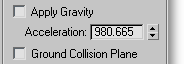
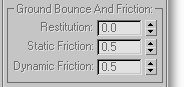
PhysX World HelperPath: Particle View > Click or add a PhysX World operator > Click the => button if available, otherwise click Create New Driver and then click =>. Path: Modify panel > Viewport > Select a PhysX World helper. Path: Create panel > Helpers > Particle Flow > Click PhysXWorld > Drag out the box-shaped helper in the viewport. The PhysX World helper, also known as a driver, defines the global properties of a simulation. Note: The icon of a PhysX World driver cannot be animated, nor can the parameters of a PhysX World driver. 3ds Max allows you to animate the PhysX World driver icon but the gravity direction and ground location, as defined by the icon placement and orientation, are defined by the icon location at frame 0. See also PhysX World Operator. Interface – Parameters rollout The PhysX World Helper interface comprises two rollouts: Parameters (this section) and Advanced Parameters. Note: Using the 3ds Max standard Hide function on a PhysX World helper also hides any associated PhysX Glue bindings. To hide either without affecting the visibility of the other, use the Hide Visual Representation settings at the bottom of this rollout. Apply Gravity - Enables gravity, the most commonly used force in simulating real-world physics. The direction of the gravity force is determined by the orientation of the PhysX World helper icon. When on, an arrow appears at the center of the icon to indicate the gravity force direction. Acceleration - The magnitude of the gravity force. The default value corresponds to the gravity force on Earth at sea level. Note: When you add a PhysX World helper, the software determines the default Acceleration value based on the current Units Setup (Customize > Units Setup > System Unit Setup). If you change the Units Setup (Customize menu) after creating the PhysX World helper, the Acceleration value no longer corresponds to the standard gravity force. Ground Collision Plane - Creates an invisible ground plane with which particles collide. The ground plane is not associated with any geometry; rather, the PhysX World helper's icon position and orientation define the plane. When on, a cross icon appears on one of the icon faces to specify the plane of the ground collision. Ground Bounce And Friction groupSet the dynamics properties for the ground plane when Ground Collision Plane is on:
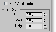
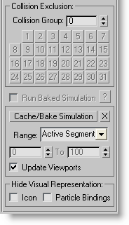
Note: The Box#2 interface does not have the ability to define these parameters for each material pair. Instead, the parameters are defined on per-material basis. The actual parameters for object-to-object interaction (the material-pair parameters) are calculated as an average of the parameters for each material. Set World Limits - Use this option to optimize the simulation performance. When on, the simulation is calculated accurately only inside the volume defined by the helper's icon. Outside the box the simulation is quite simplified; this typically means that forces are usually calculated but collision detection is not, because it's the most expensive part of simulation calculations. With large particle count (thousands of particles), you can speed up calculation of the simulation significantly if this option is on; in some situations by an order of magnitude. The calculation speedup comes at the price of memory: If World Limits are known (when the option is on), the PhysX simulation engine makes a spatial analysis of this volume in relation to particle location. Icon Size - Set the size of the helper icon in world units. Usually, the size of the icon does not affect the simulation; it just shows the gravity direction and ground collision plane. The only exception is when Set World Limits (see following) is on. Collision Exclusion groupBy default, all items in the simulation are assigned to Collision Group 0, which means they collide with everything in simulation. To optimize calculation and for other reasons, you can assign a specific collision group to items with the PhysX Shape and PhysX Collision operators. In the Collision Exclusion group you can define "do not calculate" collisions between specific collision groups. If you know that two sets of items are never going to be in the proximity of each other, or you don't care whether those items pass through each other, you can define exclusion for a pair of collision groups. Do this by setting the Collision Group value to one Collision Group ID value, and then selecting a button with the other Collision Group ID. The button stays active (yellow), thus identifying a pair of collision groups with collision exclusion. Run Baked Simulation - When on, the simulation runs from an existing cache; available only after using Cache/Bake Simulation (see following). You can play back a baked simulation with Time Configuration > Real Time on or off. A non-baked ("live") simulation can run only in non-Real Time playback mode. This is because "live" simulation needs a specific time-step integration that is unavailable in Real Time playback mode. The software does not prevent you from running a "live" simulation in Real Time playback mode without a cache, but the result will be inconsistent and sometimes wrong. ? - Opens a dialog with statistics for the baked simulation, including the amount of memory it consumes. The baked simulation is stored with the scene file. Cache/Bake Simulation - Calculates the simulation in the defined time interval and stores the simulation data in an interface cache. Once the simulation data are stored in a cache, Run Baked Simulation becomes available. To remove the baked simulation, thus preventing overlarge scene files, click the X button. The time interval to calculate the simulation for baking is defined by the following parameters: Range - Set the frame range for caching the simulation to the Active Segment, as shown on the animation frame range below the viewports, or to Custom Range as defined by the two time spinners for Start and Finish. You can also define whether to update viewport while simulation is calculated with the Update Viewports - When on, updates the viewports as the simulation is calculated. Turn off for faster calculation, but without visual feedback. Keep in mind that you need not calculate the simulation in one continuous "go." You can calculate sections while changing simulation parameters for different takes. This way you can cache simulation with one set of parameters for the frame range 0 – 50, and with different parameters for frames 51 – 100. Then, when you run the baked simulation, you might see a change in motion at frame 50. Hide Visual Representation - This group contains switches for toggling the visibility of the PhysX World helper icon and the PhysX Glue bindings in events controlled by the PhysX World helper. When on, the respective element or elements do not appear in the viewports. Interface – Advanced Parameters rollout Subframe Type - The simulation uses the Particle Flow System integration step as a timing parameter for each step of the simulation. To add extra precision for simulation purposes, you can subdivide the system integration step into smaller simulation intervals in one of two ways:
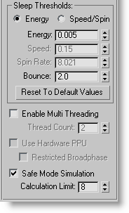
Tip: For stable, reproducible simulation in conjunction with PhysX Glue, it is strongly recommended that you use the Fixed subframe type. Subframe Factor - When Subframe Type=Fixed, this setting tells Particle Flow how to subdivide the system integration step into smaller simulation intervals. A Subframe Factor value of 1 means that no additional subdivision occurs; 2 means that the main integration step is halved for physics simulation purposes, and so on. Tip: If you encounter instability in your simulation, such as objects moving when they shouldn't, you probably need to increase the Subframe Factor value. The general rule of thumb for setting Subframe Factor is to double the Max Binds p/Particle value and add 2. So, if Max Binds p/Particle is 4, then Subframe Factor should be set to Sometimes you can get away with a lower Subframe Factor value, depending on the overall complexity of your simulation. In general, you need to experiment to find the best setting. Time Scale % - Use this setting to speed up or slow down the simulation time. You can animate this setting, so, for example, you could run the simulation at normal speed initially and then, for a few frames, decrease Time Scale to a low value for a "bullet time"-type effect. Note: For best results, when you change the Time Scale value, adjust the Subframe Factor value (see preceding) by a similar factor. For example, if Subframe Factor is 18 and you set Time Scale to 50.0 (from the default 100.0), change Subframe Factor to 9. Not doing so can alter the simulation output noticeably. Sleep Thresholds - To optimize calculations, the PhysX engine places simulation elements in an inactive or sleeping state if they move slowly or have low energy. In this state, a particle no longer participates in the simulation, and stays asleep until touched by an active particle via collision, or one of its properties is changed (usually by an Output PhysX suboperator). This can help to reduce jitter when particles are almost static. The Sleep Thresholds group settings specify the method used and define the minimal values for particle properties for when a particle will be put to sleep. To define how the system determines when to put particles to sleep, choose one of the following:
Use the following settings to specify the values below which a sleep state is defined, depending on the method (see preceding):
Reset To Default Values - Returns the Sleep Thresholds group settings (except the Energy vs. Speed/Spin radio button) to their default values. Enable Multi Threading - If your computer has multiple CPUs (real or virtual) and no PhysX hardware, you can speed up simulation processing by enabling this switch and setting Thread Count to the number of CPUs to use for calculating the simulation. The software does not check for the accuracy of the Thread Count value. Note: Due to scene complexity, some simulations cannot be split easily into multiple cores; in such cases, with multithreading a small performance penalty might result. Use Hardware PPU - If NVIDIA PhysX hardware is present on the computer, this option becomes available and you can turn it on to instruct the PhysX World driver to run the simulation on the hardware. Note: The PhysX hardware can hold only one simulation at a time. Thus, if your particle system contains multiple PhysX World drivers for several concurrent simulations, only one of the drivers can use hardware for simulation. Also, other plug-ins that use PhysX hardware can interfere with the ability of PhysX World driver to use the hardware for simulation.
There are other limitations imposed on hardware scenes:
Safe Mode Simulation - When on, you can define the maximum time, in seconds, that the simulation engine can take to calculate an integration step (see Calculation Limit, following). When off, there is no time limit for calculating a simulation step, and if the simulation is successful, it can run marginally faster than when on. Default=on. This option can help in certain situations in which the PhysX engine might fall into an infinite loop or cannot resolve an integration step in a reasonable amount of time (for example, when the particle size is much larger than the Birth Grid > Grid Size setting). In general, especially when first learning Box#2, keep Safe Mode Simulation on. With experience, you can avoid most of the pitfalls of the PhysX engine, and can then turn this option off. You can also edit the ParticleFlowToolsBox2.ini file to turn off this option by default (see Customizing Particle Flow Tools: Box#2).
|